Control Points Properties
Use control points to to align 3D models to panoramas.
When a 3D model is selected in the Tour Browser, the Viewer Modes change to accommodate the 3D model. The Control Points Viewer Mode is also available for panorama nodes in the case you’d like to start adding controls to a panorama.
Tour Node
Select an option to filter the control point result which will show in the Unlinked table below.
All – Select to show all control points in all nodes. Since All does not apply any filter, this could lead to a very long Unlinked list (control points not yet paired or added to the current node). If that’s the case, one of the options below would be better suited.
Linked – This will only show control points from nodes that are linked to the current node via a hotspot.
Selected – This will only show the control points from the nodes selected in the Tour Browser.
Tour Panoramas – Choose a specific node to compare control points. Only the control points that exist in this panorama will appear in the Unlinked table, if there are any.
Switch to this node
When a Tour Node is selected, this button will appear. Click it to jump to that node.
Align Camera Point
Click the Align Camera Point button to optimize the camera position, which is calculated from the control points. The button appears when a specific tour node is chosen in the Tour Node menu and either the current node or the chosen node is a 3D model (one panorama and one 3D model). At least 3 control points are needed to find a camera position (5 when aligning along view lines, see below).
Press and hold the button to open a menu with three additional optimization modes:
with Panorama Leveling – Optimizes the camera position and also levels the panorama. If leveling the panorama clearly reduces the average control point error, a dialog will ask which leveling reference to trust: the 3D model’s level (the panorama leveling is adjusted) or the panorama’s level (the 3D model leveling is adjusted instead).
with Model Leveling – Optimizes the camera position and also levels the 3D model.
along View Lines (Splats) – For Gaussian splats. A double-click in a splat rarely lands at exactly the right depth, but the feature you clicked is somewhere along your line of sight, and that is what this mode trusts: a control point only has to line up with the line it was picked along, not with its exact position. It needs at least 5 control points and works best when you pick them from two or three different viewpoints; from a single viewpoint the lines cannot tell how far the camera is from where you picked, and that distance is then taken from the picked positions. When the optimization converges, the control points are moved onto their view lines to where the camera sees them, so a later optimization in any mode starts from the right positions. Undo reverts the camera point and the control points together.
When the current node is a 3D model and the Tour Node menu is set to All, an additional Align all Camera Points button appears. Click it to optimize the camera positions of all camera points of the 3D model in one go.
Control Points Viewer
This viewer shows the locations of the selected control point, in the node (or a node) from the dropdown menu above. If the node containing the control point is a 3D model, the viewer shows the 3D model instead of a panorama. When one of the filter options (All, Linked, Selected) is chosen in the Tour Node menu, the name of the node currently shown is appended to the viewer’s title.
Control Points Tables
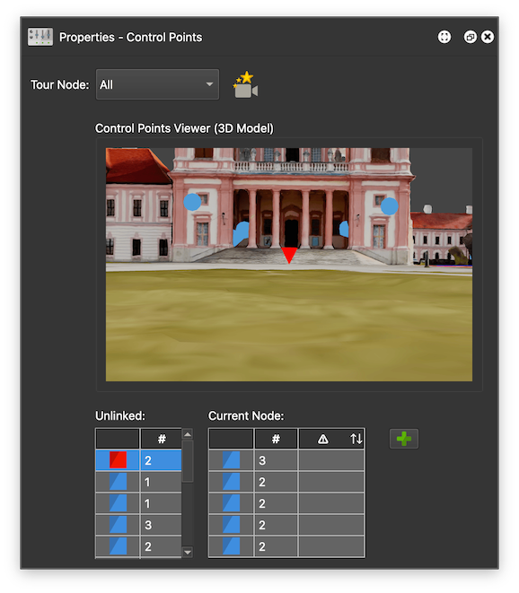
The first column shows the control point. The currently selected control point will be red. Hovering over the others will highlight which nodes the control points also exist throughout the project.
The second column (#) shows the number of instances of that control point, in all nodes of the project.
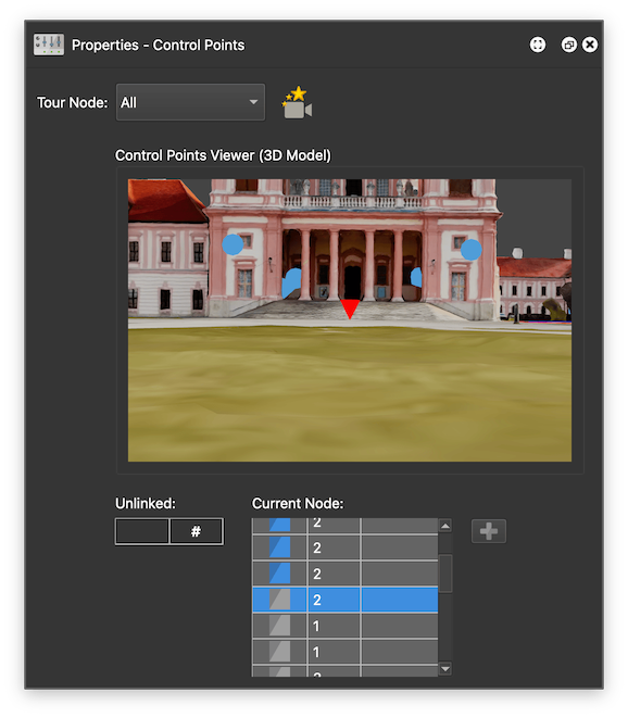
The third column in the Current Node table is the Alignment Deviation in Degrees. It shows how far off the camera position is for that control point. Ideally you want to get as close to 0 as possible. Align the camera point to try to get a better deviation by clicking the Align Camera Point button. If a control point is really far off, delete and try again (you may have misplaced it).
Double-click a control point that exists in the current node to center the Viewer on its position.
Right-click a control point for the following options. When several control points are selected, the command applies to all of them, and each keeps its own description when you assign a symbol, and its own symbol when you edit the description.
Assign Symbol – Assign the control point a symbol for easier identification.
Add/Edit Description – Add a description to the control point. This will be visible in the model when the mouse hovers over a control point in the Viewer, and also in the Control Points Viewer.
Remove Control Point from Project – Remove the control point from the current node and anywhere else in the project it occurs. With several control points selected, this command is called Remove Control Points from Project.
Alignment Deviation in Degrees
This column shows how far off the camera position is for that control point. Ideally you want to get as close to 0 as possible. Align the camera point to try to get a better deviation by clicking the Align Camera Point button. If a control point is really far off, delete and try again. Click the column header to sort the table by deviation. After optimizing along View Lines, the deviation is measured to the control point’s view line rather than to the point itself.
Unlinked
This table populates with control points that have not yet been placed in the current panorama. Once these points are placed in the current panorama, they will move over to the Current Node table.
Click a control point and it will turn red and appear in the Control Points Viewer.
Current Node
This table populates with control points, that have an instance / are placed in the current node.
Add Control Points
Whenever there is a control point active (selected in one of the tables), double-clicking in the viewer will place that control point in the current node. If you instead want to create an entirely new control point in the current node, press this button. It will deselect the current control point. Then, double-click in the Viewer to add the new control point. The button is only enabled while a control point from the Unlinked table is selected.